- 您现在的位置:买卖IC网 > Sheet目录332 > IR2304SPBF (International Rectifier)IC DRIVER HALF BRIDGE 8-SOIC
�� �
�
�Data� Sheet� No.� PD60200� rev� B�
�IR2304(S)� &� (PbF)�
�Features�
�?� Floating� channel� designed� for� bootstrap� operation�
�HALF-BRIDGE� DRIVER�
�Product� Summary�
�?�
�?�
�?�
�?�
�?�
�?�
�?�
�?�
�?�
�to� +600V.� Tolerant� to� negative� transient� voltage�
�dV/dt� immune�
�Gate� drive� supply� range� from� 10� to� 20V�
�Under� voltage� lockout� for� both� channels�
�3.3V,� 5V,� and� 15V� input� logic� input� compatible�
�Cross-conduction� prevention� logic�
�Matched� propagation� delay� for� both� channels�
�Lower� di/dt� gate� driver� for� better� noise� immunity�
�Internal� 100ns� dead-time�
�Output� in� phase� with� input�
�Available� in� Lead-Free�
�V� OFFSET�
�I� O+/-� (min)�
�V� OUT�
�Delay� Matching�
�Internal� deadtime�
�t� on/off� (typ.)�
�Package�
�600V� max.�
�60� mA/130� mA�
�10� -� 20V�
�50� ns�
�100� ns�
�220/220� ns�
�Description�
�The� IR2304(S)� are� a� high� voltage,� high� speed�
�power� MOSFET� and� IGBT� driver� with� inde-�
�pendent� high� and� low� side� referenced� output�
�channels.� Proprietary� HVIC� and� latch� immune�
�8-Lead� PDIP�
�8� Lead� SOIC�
�CMOS� technologies�
�2106/2301/2108/2109/2302/2304� Feature� Comparison�
�enable� ruggedized� monolithic� construction.�
�The� logic� input� is� compatible� with� standard�
�CMOS� or� LSTTL� output,� down� to� 3.3V� logic.�
�The� output� driver� features� a� high� pulse� cur-�
�rent� buffer� stage� designed� for� minimum� driver�
�cross-conduction.� The� floating� channel� can� be�
�used� to� drive� an� N-channel� power� MOSFET�
�or� IGBT� in� the� high� side� configuration� which�
�operates� up� to� 600� volts.�
�Part�
�2106/2301�
�21064�
�2108�
�21084�
�2109/2302�
�21094�
�2304�
�Input�
�logic�
�HIN/LIN�
�HIN/LIN�
�IN/SD�
�HIN/LIN�
�Cross-�
�conduction�
�prevention�
�logic�
�no�
�yes�
�yes�
�yes�
�Dead-Time�
�none�
�Internal� 540ns�
�Programmable� 0.54~5� μ� s�
�Internal� 540ns�
�Programmable� 0.54~5� μ� s�
�Internal� 100ns�
�Ground� Pins�
�COM�
�VSS/COM�
�COM�
�VSS/COM�
�COM�
�VSS/COM�
�COM�
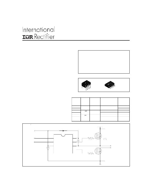
�Block� Diagram�
�Vcc�
�up� to� 600V�
�HIN�
�LIN�
�LIN�
�HIN�
�VB�
�HO�
�www.irf.com�
�VCC�
�COM�
�IR2304�
�VS�
�LO�
�TO�
�LOAD�
�1�
�发布紧急采购,3分钟左右您将得到回复。
相关PDF资料
IR2308SPBF
IC DRIVER HALF BRIDGE HV 8SOIC
IR3101
IC POWER MODULE 1.6A 500V 11-SIP
IR3103
PWR MOD 180W GATE DRIVER 11-SIP
IR3519STRPBF
IC MOSFET GATE DRIVER SON-8
IR4427STRPBF
IC DRIVER DUAL LOW SIDE 8SOIC
IRAM136-1061A2
IC MOSFET DRIVER
IRAMS12UP60A
IC MOSFET DRIVER
IRDC3622D
BOARD EVAL W/IR3622MPBF DUAL OUT
相关代理商/技术参数
IR2304STRPBF
功能描述:功率驱动器IC Hlf Brdg Drvr Soft Trn On NonInvrt Inpt RoHS:否 制造商:Micrel 产品:MOSFET Gate Drivers 类型:Low Cost High or Low Side MOSFET Driver 上升时间: 下降时间: 电源电压-最大:30 V 电源电压-最小:2.75 V 电源电流: 最大功率耗散: 最大工作温度:+ 85 C 安装风格:SMD/SMT 封装 / 箱体:SOIC-8 封装:Tube
IR2308
制造商:IRF 制造商全称:International Rectifier 功能描述:HALF-BRIDGE DRIVER
IR2308PBF
功能描述:功率驱动器IC Half Bridge Drvr Hi Volt & Hi Speed RoHS:否 制造商:Micrel 产品:MOSFET Gate Drivers 类型:Low Cost High or Low Side MOSFET Driver 上升时间: 下降时间: 电源电压-最大:30 V 电源电压-最小:2.75 V 电源电流: 最大功率耗散: 最大工作温度:+ 85 C 安装风格:SMD/SMT 封装 / 箱体:SOIC-8 封装:Tube
IR2308S
制造商:IRF 制造商全称:International Rectifier 功能描述:HALF-BRIDGE DRIVER
IR2308SPBF
功能描述:功率驱动器IC HALF BRDG DRVR 600V 10 to 20V 540ns RoHS:否 制造商:Micrel 产品:MOSFET Gate Drivers 类型:Low Cost High or Low Side MOSFET Driver 上升时间: 下降时间: 电源电压-最大:30 V 电源电压-最小:2.75 V 电源电流: 最大功率耗散: 最大工作温度:+ 85 C 安装风格:SMD/SMT 封装 / 箱体:SOIC-8 封装:Tube
IR2308STRPBF
功能描述:功率驱动器IC Half Bridge Drvr Hi Volt & Hi Speed RoHS:否 制造商:Micrel 产品:MOSFET Gate Drivers 类型:Low Cost High or Low Side MOSFET Driver 上升时间: 下降时间: 电源电压-最大:30 V 电源电压-最小:2.75 V 电源电流: 最大功率耗散: 最大工作温度:+ 85 C 安装风格:SMD/SMT 封装 / 箱体:SOIC-8 封装:Tube
IR-2-330-10
制造商:Vishay Dale 功能描述:Inductor, Ferrite Core, 330uh, 10±%
IR2339
制造商:Sharp Microelectronics Corporation 功能描述:IR2339